Daedalus SSDR


Daedalus Single Seat Deregulated Aircraft Development
Follow the development of a new, all metal Single seat de-regulated touring aircraft being designed and built by Chris Antrobus in East Sussex. with a roomy, wide cockpit, rugged airframe, long range and practicality in mind.
The aircraft features tapered outer wings, all moving stab and fin.
I developed interest in fixed wing flight at age 7 after leaning heavily on my parents to buy me my first RC aircraft, then after watching the TV series "A Plane Is Born" it became my goal to design and build my own aircraft. I started out with a wood and fiberglass design owing to material costs, but didn't like the way it was going, and had since taken up employment and specialised in sheet metal work. So the design you see here is the result. If anyone would like to discuss it or their own SSDR please get in touch I'd love to swap stories and ideas, or I can offer some level of design service for your own.
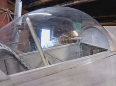
I managed to fabricate my MK1 SSDR canopy, which worked better then I could have hoped. There are some imperfections and a lot was learned from the experience so next one should be even better however the front dome is near enough perfect and has virtually no optical distortions and is uniform. The rear is a slightly different shape on one side, and has a dent from a shrader valve that fell in




I cleared the upstairs space and stuck everything made so far on the airframe (A first just to have both wings on at the same time)
I then rolled it onto a set of scales, as I wanted to check how overweight the airframe was so far and how much weight I need to lose to fly it.
I originally designed for a 150kg empty weight, and had resigned myself to a more likely 165-170kg, with parachute that would give 320Kg max takeoff and with my weight around 50kg load spare fuel and baggage.
Left wheel 60Kg
Right wheel 58kg
Tail wheel 12kg
Total 130Kg!!!!
Still to add are canopy, cowlings, fairings, instruments, engine controls and paint plus finishing touches. I think 20-25kg for the lot is not unrealistic but things are looking very promising.
Further to this the MK2 version I can make around 15-20% lighter through design refinements.
I've realised there is an oven on site big enough to blow my own canopy!
So the project isn't a throw away or even close to one!
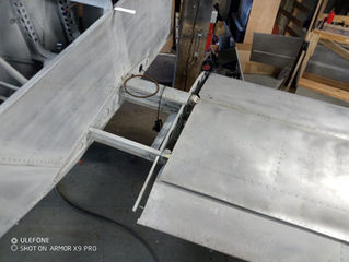
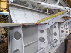
Rear spar pickup needs making, its just hanging there at the moment from the front pins.




The undercarriage has been upgraded considerably. I decided the wheels machined up from bar (4.5") the largest I could source, and the sack barrow tyres, about 9" diameter, where just too small for the scale of the aircraft, rabbit hole threat. So I aquired some ultralight wheels with incorporated disc brakes. They are about 13" diameter and weigh the same as my machined wheels.
I originally replicated the square block, box section undercarriage design that is utilised on my Menestrel, this essentially has an aluminium block riveted to the top of the leg strut, that slides inside the box section top leg, it retains allignment and holds the rubber shocks on the top.
I decided the scale of the new wheels, and the small box section I opted for, would provide too much torque for the sliding block, so I designed, fabricated, welded on bushings, and fitted torque links to each leg which I'm quite pleased with.
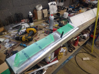
Work has been progressing on the second wing.



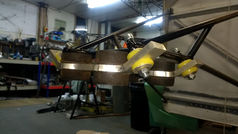
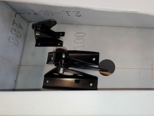
Based on the feedback I received on the mounting, combined with my dissatisfaction with available space, I tracked alternative mounts and did a rework. I got some second hand but serviceable Lycoming and continental mounts. As I could fit the Lycomings I opted for them as they are very substantial. Moving the cross mounts to an underslung position gave much more clearance, I made up larger cross mounts with bigger clearance holes on the side bolts, so they can be insulated as well. I was planning to start routing the rudder pedals, and noticed in my somewhat hasty decision to put the arms on the hingepoint, the stabilator obstructs them entirely.


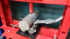

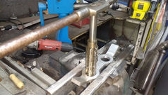



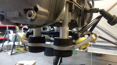


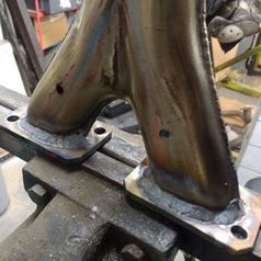
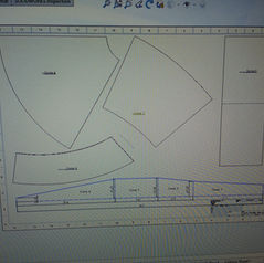
Starting on the exhaust, I cut up the monstrous Rotax head unit, made much lighter mounting plates, blasted what was left, cut off the connection point, and welded back together with out the excessive flanging. I used an exhaust calculator to produce dimensions to suit the engine specs, and printed off templates, making up a rough and ready expansion chamber exhaust. I will borrow an original Rotax to give a performance baseline and see how it runs. Below: Mig welded experimental exhaust, still a lot to add its short about 4 sections.





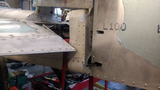
At the same time I noticed some workshop rash had put a large scraped dent in the rudder, so I drilled the skin off, annealed and planished the main dent out, stress revealed as much as possible with a quick bead blast and re anneal, then put a doubler on, which gave a reasonable finish on the repair. I moved the arm down and included a reinforcement doubler to move the load into the skins in shear rather than try torque through the thin spar.
Pictures show the result and fin in position.



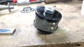
The fuel tank is now semi mounted, I've welded in outlets for it, and made this little filter to install inside the tank.



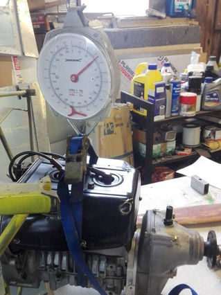
The engine of choice for the aircraft is the Rotax 503, air cooled two stroke engine. The weight came in at the expected 30.5kg, need to try make a lightweight exhaust for it, as the stock one weighs I think up to 5kg.



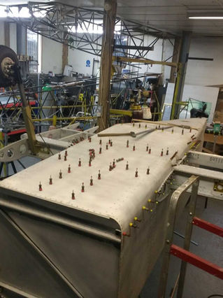
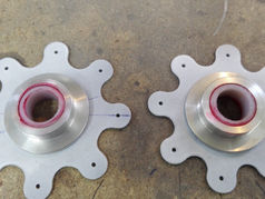
As of September 2020, the controls and joystick are finalised, and the lower skin in position with, thanks to Simon Knights help, about 40% riveted on thus far. The laser cut brake discs where lost by UPS, so the company is kindly cutting more off ASAP.
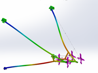
I've just designed the engine mount in detail, I had an original design which was inspired by another installation, but I wasn't happy with the stressing. So the MK2 is simpler, lighter and twice as strong. See images attached for the stresses and configuration changes. Will start fabricating this week. See the MK1 then MK2 versions loaded in the same way.
Top Left - MK1 engine mount config.
Top Centre - MK1 Stresses, this was after adding the cross bracing at the bent point of the upper tubes. 6G loading, full engine torque, and gyroscopic loading.
Top Right - MK 2 Displacements, 3mm max basically.
Bottom Left - MK2 configuration
Bottom Centre - MK2 Stresses, same loading as the MK1 at 6G, full engine torque and gyroscopic load.




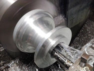
Tail Wheel Time. I needed to make up something so I can close up the back of the fuselage of the Daedalus SSDR. So machine up a block, this is modelled on the standard centre locking, to a point, free castoring design, with a sprung key which holds the wheel straight when not turning hard. The wheel was a solid rubber trolley wheel, Bored out the plastic plain bearing and inserted a pin bearing holding steel plug. Turned the wheel down on the lathe with a parting tool and planar file. Couple Dural lead springs, the lower is slotted to allow more initial play, so slides along the bolts to a point. Now finishing up the tail end to close it up, tightning and split pinning all the bolts, tying down the wires, finalising part set rivets, and adding a few little reinforcements.


Main wings and control column. I've been getting into the gritty of the first wing. Finalising the controls and split pinning all the bolts etc. So not much visual progress. The flap had to be drilled open again, and replaced the outer track bolt mounts, as the outer spar was twisted and misaligned the mounting, so the tracks fought each other. Corrected and working beautifully now. The trailing edge on the aileron had to be cut, and design matched to the same as stab and flap design, with a V channel insert riveted from both sides, as the bench alignment, did not match the wing alignment! The fuselage also now has these nice bushings for the stabilator pushrod.


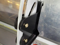

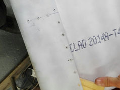
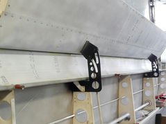
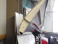

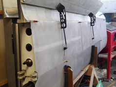
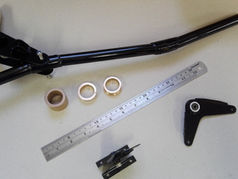
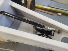
The Trim arm is semi installed, and the control column is fabbed, painted, unpainted re fabbed, the intermediate bell-crank on the aft spar, designed, made and installed. The Oilite bushings, are machined, bonded in place, and reamed with one of my hand reamers, the fit and play is magnificent I was worried it would end up floppy. I shortened the pivot length of the control column as the amount of throw was insufficient, now got a good 25cm of movement. Disaster at the end of Friday though, as I needed to shorten the column to bell-crank pushrod, and had the tail in one direction, and the column carelessly in the other, and cut it 2 inches too short, so have to make another. Sigh, I've decided on an electric trim, and ordered a micro linear actuator to fill the role.


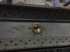


Put the wing on to check it still fits, and it looks the buisness, need to put more effort into the finishing details the flaps and ailerons are looking a bit scruffy and slapdash.
Was very pleased with my fuel tank I build, turns out I can weld ally quite well! plotter still not running so had to manually plot out the curves as the tank is curved top and bottom and tapered.
Simon came by a couple times to help with the top skin riveting, and hilarity ensues. Also put the tail on to show him how its looking.
Machined up the second wheel, but I've lost the second bearing set, happens when things get dropped for a long time.
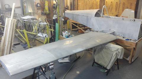
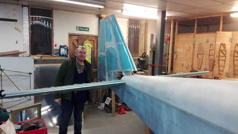

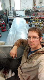
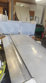
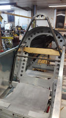
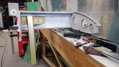
Fuselage coming along at a rapid pace, roll bar designed and fabricated, will do nicely to mount restraints and possibly even a ballistic recovery system. Seat is partly in, and the main carry through spar coming together at the same time, as the seat forms part of it. And wife took a bunch of pics so you can see how it is shaping up. Its massive! Going to be the most spacious single seater ever built!
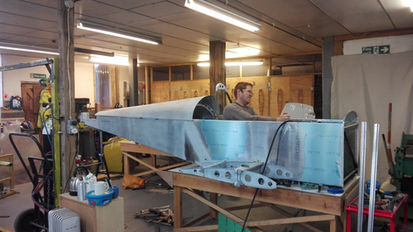


Smudlets. I have been working on an English wheel experiment, and have produced what I call 'Smudlets' to keep the mud off the wings, they came out quite well and even, but one cracked on top without adequate annealing so needed a plate repair, regardless should do the job and look cool.


The stabilator is now fully mounted, the bearings pressed in and bolted on. I added a steel doubler to the bulkhead the tailplanes all bolt onto, as the 18swg ally was clearly not up to it alone, with all the torque 3.5ft of stab could do either side. I also made up a mass balance arm, as I hadn't really planned for it, that wraps around the main spar and rivets through the caps. Future versions will have spacer blocks and bolt through the spar. This took quite some designing to fit in the small space and take the load.


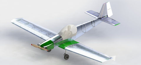
SSDR Mk2 Design. I am about half way through designing the MK2! Couple of renders shown. I've taken all lessons learned from building the MK1, thicker wing section to lighten the spars, simpler wing roots, tracked flaps, much neater then the, what seemed a good idea at the time, external hinges. The fuselage is far neater, rounded, and more space and weight efficient, as the MK1 could possibly get away with being a tandem.

Stabilator lifting bell crank. I've decided the bearing mountings on this are too light weight, so I've ordered some larger bar and will make a beefier one.


Fuel tank build and tank ring welded in. I'm getting very pleased with the alloy weld results I can get reliably.


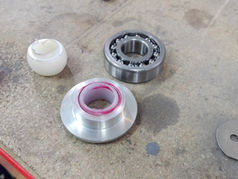
Push Rods. I made some nylon in ally ball bearings as the steel self aligners I bought where too heavy, and have been building the first aileron with integrated ball bearing assemblies for longevity. None of these parts where particularly designed so mostly making it up as I go.
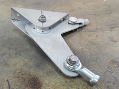



Undercarriage
In the few moments I've had recently between trying to progress the main projects I have been working on the flap slot and undercarriage for my SSDR, tyres are on order (Heavy duty sackbarrow tyres) and I've designed wheels which I will turn up here with bearings, atv disc brakes and callipers on order.
Wheel I made for my SSDR, 4.5" Dural Bar, with a heavy duty wheelbarrow tyre. Looks the business but the tyre surviving is questionable, will be building a rig on the car to 'Test' it. But it is all the Cri Cris fly on.
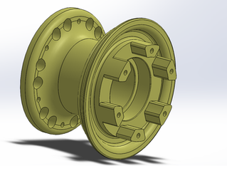


Second wheel all machined up, I think these need a bit more weight reduction they are very heavy for the aircraft scale. Also I think the quad bike hydraulic brakes are very heavy and complete overkill, going to source a bicycle set like most other microlights.
The first flap has been mostly assembled, it was very satisfying when I positioned and fitted the main flap hinge to the flap itself, and pinned in place for it all to line up perfectly.
The Fuselage Rear Spar carry through is now cut into the fuselage and fitted to the ribs port side. It really gives the impression of how much space there will be, also think I can have a lower canopy then I envisioned. The rear spar pickup is also measured up, designed and fitted to allow the wings to fold about the top main spar pin.
On a side bar, had to pop to the model shop to buy some fiberglass and found a rare as the proverbial number drill stand with complete set of drills! £10, as well as two imperial micrometers for £2.50 each. Bought in an immaculate tube wall thickness micrometer.


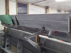


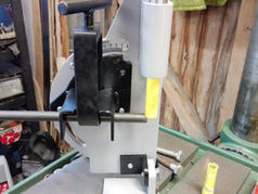

Folding Wings? I always wanted the design to feature folding wings, but avoided it owing to potential complexity, so that being said with a simple redesign of an external hinge point on the rear spar which can be faired over it can do something a bit like this! would be a handy additional sell point I think?!
Ailerons would be drooped as a result of the positional change.
Fuselage Assembly Continued. This was the point when the, essentially two sides and a carry through spar, became an aircraft fuselage, and took an incredible amount of time and work. I was essentially designing most of this as I went and developing methods to fabricate the large curved sheets as I went. As well as picking how much reinforcement was required for the floors and stiffeners in the skins.


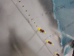
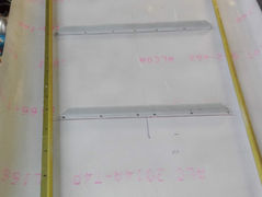
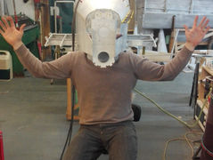
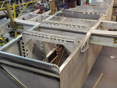


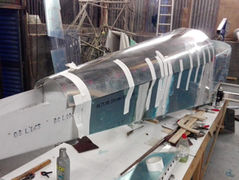


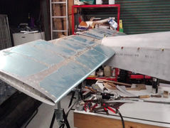

Outer Wing Fabrication. Taking the formed ribs and built up spars, and combining them and fabbing the skins was the most satisfying part of the build so far, forming the providers of flight has a certain something about it that makes you feel so good! Finishing off all the fiddly bits like flap and aileron hinge mountings, less so. They are a bit crude and will be refined on the MK2.
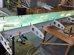


Simon Knight nicely came round Wednesday evening and we riveted up the top wing skins along the spars and ribs I couldn't reach alone, I've never done any two man riveting but we got on well and only had about 3 rivets which needed any reworking. Two cups of tea and a late evening followed by a haggis dinner at home.
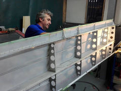

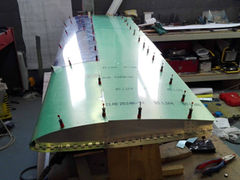


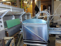
Fuselage Ribs & Center Section Assembly. These where initially made about 2 years ago but sat in halves until now, joggled and riveted together, the larger ones which go into the center section needed modifying with countersunk rivets for the spar to sit flush against them.
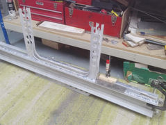


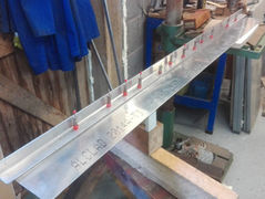
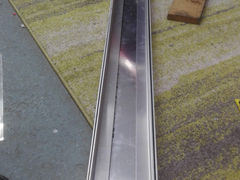
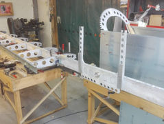
Rudder Assembly. Not many parts in all but getting it together straight, and solving a self made issue of, putting the rudder fins on the wrong side of the spar gave an unexpected opportunity to simplify construction. The Rudder spar was designed to be hidden inside the skins, but carelessly putting it on facing out, meant simplified construction and the use of solid rivets, superior to pop. A slight fold, to angle the skins inward, and offset hinges, results in a very nice gap sealed rudder that Frise style folds into the fin when deflected.

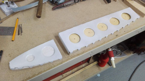
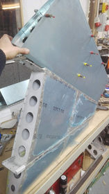


Stabilator Assembly. This was the first major assembly that came out of the originally manufactured collection of parts.
As the design is an all moving stab, to provide adequate authority for the absurdly low stall speeds required by the SSDR category of 35kts, an extremely rigid spar which can take all the bending loads of such a large plane, and torsion about the 1/3 chord point.
For simplicity the caps are not layered construction but one piece 16swg 2024 T3 and the process of punching the lightening out on the fly press was very time consuming. the sheet sizes available meant that the outboard portions are joggled and riveted on with doublers. The forces involved in direct push pull controls was too high, so I designed it to use levers under the tail and an up down connection acting on a cross tube aft of the hinge resulting in very low control force requirements.

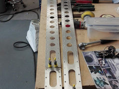


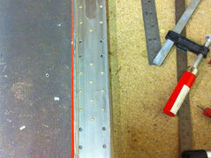


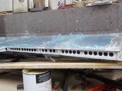


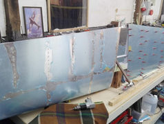

Assembling the Main spar. I bought a 6ft folder specifically for this task originally, it does the job beautifully for 22swg L163 but sadly not much heavier, so I need a heavy duty one realistically, still total spar length in the region of 10ft so a joggle and join needed.
The laminates are 3mm 2024 T3, and taper away as you can see, I did all these rivets with a support block, a hammer and a punch. I recently bought a x2 rivet gun and what a waste of time it was doing it manually!
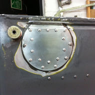
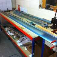

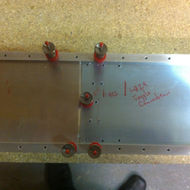

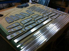
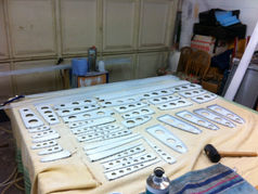
Wing Ribs and Spar. All the ribs for the wings, fuselage and empennage are hand formed over ply wood formers, having an A0 plotter I can print of full size drawings, check the scale and glue straight onto boards, cut out, sand, then cut the ally to shape and hammer away. The spar caps are 3mm 2024 and I designed them to be inherently straight 1" strips tapered at the outboard end, but in hindsight this was a mistake as it required complex root attachments and simply to have guillotined tapered strips with something closer to a 1 3/8" thickness at the root to allow diameter for the bolt to pass straight through would have been much simpler, updated for any future models.
